inner rotor motor
Inner rotor motor explained in practice: operating principle, application areas, typical faults as well as guidelines for testing, selection and safe operation.
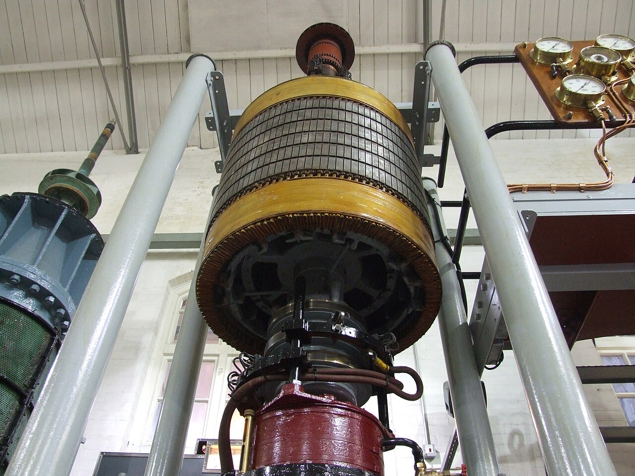
Photo: Les Chatfield from Brighton, England, CC BY 2.0, via Wikimedia Commons
In an internal rotor motor the rotor sits inside the stator and delivers torque via a central shaft. For maintenance and selection it is not enough to look only at the external shape. What matters is how field, rotor, supply and load interact in the specific drive.
This design is especially associated with classic shaft output, well‑established bearing and versatile mechanical integration. It is used, for example, in industrial drives, servo drives, pumps, machine tools and numerous compact drives. Motors that look similar can differ significantly electrically and thermally, which is why data should never be taken from a neighboring model.
What is an internal rotor motor?
The type / design designation therefore describes not only an external shape, but above all the way the magnetic field is generated and converted into mechanical motion.
In everyday use the distinction is important because start behaviour, controllability, maintenance and possible faults depend heavily on the motor principle. Characteristic are classic shaft output, well‑established bearing and versatile mechanical integration.
How an internal rotor motor is constructed
Fundamentally this includes at least a stator, rotor, shaft, bearings, windings or other field‑forming elements as well as connection and cooling components. Which parts are electrically active depends on the type / design.
For workshop daily work this division is helpful: electrical faults are looked for in windings, connections, sensors or commutation; mechanical anomalies are more likely in bearings, shaft, air gap and rotating parts.
The functional process in an internal rotor motor
The stator field acts through the radial air gap on the inner rotor; the concrete torque generation depends on asynchronous, synchronous or BLDC principle. Torque is produced only when the magnetic conditions and the rotor position or rotor movement match each other.
Supply or power electronics must match this principle exactly. Incorrect wiring or unsuitable control can lead to poor start, high current, heating or unstable running without the motor having to be mechanically damaged.
Load in operation for an internal rotor motor
In use load torque, speed, supply and cooling together determine the stress. Classic shaft output, well‑established bearing and versatile mechanical integration are an advantage, but they do not change the fact that every motor has thermal and mechanical limits.
With variable load one should consider current, temperature, noise and vibration as related indicators. A single measurement without knowledge of the operating point is rarely sufficient for a reliable diagnosis.
Where an internal rotor motor is typically used
Typical applications are industrial drives, servo drives, pumps, machine tools and numerous compact drives. The selection results from whether the motor principle matches the required start torque, the desired controllability and the available supply.
Likewise access for maintenance, noise requirements, switching frequency and environmental conditions can be decisive. A technically suitable type / design can be impractical in another machine if, for example, cooling or control does not fit the application.
Typical fault patterns for an internal rotor motor
Possible problems are bearing faults, imbalance, air‑gap issues, winding or rotor faults and inadequate cooling. Not every symptom immediately proves an internal motor failure; supply, load machine and controller can cause very similar manifestations.
Ideally the troubleshooting should progress from a safe visual and functional check to measurements. Especially after modifications or repairs, connections, rotation direction, free run and protection functions should be checked before the motor is fully loaded again.
What to consider when selecting an internal rotor motor
For selection shaft dimensions, torque, speed, cooling, load inertia and installation situation are decisive. In addition, the manufacturer specifications of the specific motor and the intended controller must be compatible with each other.
During an inspection runout, bearings, air gap, current, temperature, vibration and shaft condition are useful. Results should be documented together with operating state and previous measurements. This creates a reliable condition picture from individual observations instead of a gut‑feeling diagnosis.
In workshop daily work a clean separation between observation and cause is worthwhile. A noticeable current, a noise or an elevated temperature is initially only a finding. Only the comparison with load state, supply, earlier measurements and the mechanical condition turns it into a reliable technical statement.
If symptoms occur repeatedly each intervention should be documented. This includes operating state, measurement point, measuring device, connection condition and behaviour after the action. This history prevents the same tests from being repeated many times without gaining insight and facilitates later cause analysis.
Safety and manufacturer specifications take precedence over general rules of thumb. Especially electrical test voltages, permissible temperatures, switching sequences and mechanical limits can differ between motor series. Where the exact execution is unknown, a deliberately open statement is better than a technically plausible but unsupported figure.
In workshop daily work a clean separation between observation and cause is worthwhile. A noticeable current, a noise or an elevated temperature is initially only a finding. Only the comparison with load state, supply, earlier measurements and the mechanical condition turns it into a reliable technical statement.
Frequently asked questions
Published 2026-10-02 · Source: Redaktion SpecCodex
→ Electric motors — terms and articles
