torque converter
torque converter: function, construction, force flow, typical wear patterns as well as notes on diagnosis, testing and maintenance in the drivetrain.
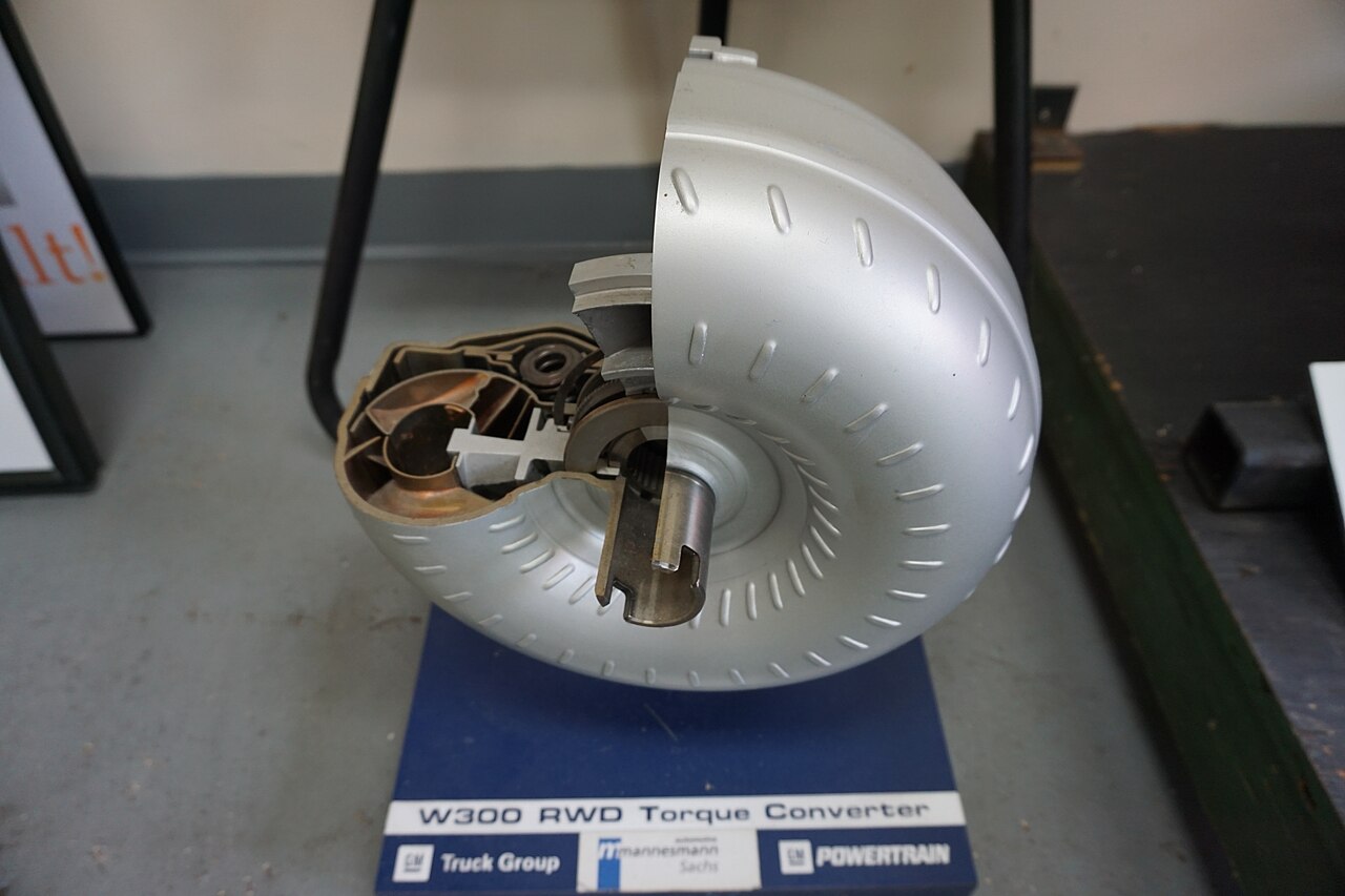
Photo: Michael Barera, CC BY-SA 4.0, via Wikimedia Commons
Pump wheel, turbine and guide wheel transmit power hydrodynamically and allow slip during start-up. The term therefore clearly belongs to the subject area drive and gearbox and describes a concrete part of the power flow between the power source and the drive or work output.
For a sound assessment, the name of the component alone is not sufficient. What matters is which parts transmit torque in the respective operating condition, which components only guide or shift, and which adjacent assemblies can produce a similar fault pattern.
Torque converter - Function and Mode of Operation
The drive is best understood via the power flow: input speed and torque are guided, translated, coupled or distributed by the respective type / design. In doing so, meshed gear contacts, friction drive, hydrodynamic flow or supported shafts can act together. It is important to distinguish between the actual function and its actuation. A component can be mechanically sound, although a cable pull, valve, actuator or an incorrect shaft position prevents its function. Conversely, a correctly controlled assembly can be internally worn. This separation is the basis of a clean diagnosis.
Torque converter under operating load
In operation, torsion, varying tensile and shear moments, speed changes and, depending on the type / design, additional radial, axial or friction forces act. When switching from tension to shear, the contact often migrates to the opposite gear teeth or joining elements. Temperature affects lubricant, seals and component clearance. Shock-like load uptake, suddenly regained traction or incomplete engagement can generate load peaks that stress the system significantly more than steady operation. Therefore, a fault pattern must always be documented together with the operating condition: gear, travel direction, load, temperature and speed often provide more information than a noise alone.
The most important components of torque converter
The typical construction includes a pump wheel, turbine wheel, guide wheel with freewheel, housing and often a bridging clutch. These parts do not form a loose side‑by‑side arrangement, but a coordinated system. Bearings set shaft positions, gears or friction surfaces transmit the load, switching elements determine the active force path and seals as well as lubrication secure the operating conditions. Even small positional changes due to bearing clearance, worn guides or loose fastenings can alter the contact of other parts. Therefore, during a repair not only the visibly damaged individual part should be assessed. Opposing surfaces, bearing locations, seals, spacer parts and adjacent connections belong to the cause analysis, especially if the damage could have arisen from misalignment or repeated impact loading.
Typical fault patterns in torque converter
High slip, overheating, poor power transmission or wear can affect the converter or the hydraulics. Additionally, metal wear, unusual contact marks, oil loss, overheating or altered clearance are serious secondary findings. A single symptom rarely proves the cause. Structure‑borne sound can propagate far through shafts and housing, and clearance adds up over multiple gears, joints or bearing locations. Therefore, it is especially meaningful whether the effect is reproducibly present only in certain gears, under tension or shear, in curves, with a warm unit or during a specific actuation. A comparison with earlier behavior or with the opposite axle side can provide additional clues, without prematurely claiming a single defect.
Torque converter: the correct test procedure
The troubleshooting starts with simple, non‑destructive tests. Oil level and visible leaks, fastenings, external actuation, electrical or hydraulic control as well as adjacent joints and bearings are inspected, insofar as they belong to the type. Afterwards the fault is reproduced under safe conditions and the power path is narrowed down. Sounds should be distinguished according to engine speed, vehicle speed, gear, pull or push operation and temperature. With the unit opened, visual inspection of tooth flanks, friction surfaces, bearings, fuses and fits is added. Measurement values for clearance, preload or pressure may only be compared with the specifications of the specific gearbox; values of similar models are not a reliable substitute.
torque converter: repair and maintenance practice
Consistent lubrication, correct oil level, free venting and sealed housing create the basic conditions for a reliable drive. Which lubricant, what fill quantity and which maintenance interval apply, however, depends on the design and must come from the manufacturer documentation. During disassemblies the installation position, markings, spacer plates, fuses and sequences should be documented. Components with surfaces that have worn against each other are to be evaluated together. A new part on a heavily worn mating surface can quickly become noticeable again. After the repair the function should first be tested under light load and then deliberately in the operating condition in which the original fault occurred.
The place of torque converter in the drivetrain
The decisive principle is to mentally follow the entire drivetrain from the engine to the wheel or working drawbar. Each stage can change speed, torque, direction of rotation or shaft position and thereby influence the symptoms of another stage. A noticeable noise at the gearbox can, for example, be introduced by a joint shaft; conversely an internal bearing clearance outside the housing can become perceptible as vibration. Good diagnosis therefore separates cause, transmission path and perceived symptom. Where the manufacturer specifies adjustment values, wear limits or test procedures, these specifications take precedence. No generic dimensions, pressures, torques or limit values are deliberately mentioned that could not be reliably substantiated without the exact type.
Frequently asked questions
Published 2026-10-20 · Source: Redaktion SpecCodex
→ Drive and transmission — terms and articles
